The development objective was to design an LTE antenna system with two individual emitters making the most efficient use of the volume available for a vehicle roof antenna module. The LTE antenna system is targeted to operate at LTE 800 MHz (791-862 MHz), 1800 MHz (1710-1880 MHz) and 2600 MHz (2520-2690 MHz). An input matching better than 10 dB at a 50 Ω load and an isolation better than 12 dB shall be obtained. In order to provide good coverage in terrestrial LTE communications, omnidirectional antenna characteristics shall be obtained in the horizontal plane. The plastic housing of a roof antenna module is used as antenna carrier where the radiating structures are bent directly on the surface of the plastic housing.
When integrating antenna systems into a vehicle, it is important to take account of the structural boundary conditions and specific antenna requirements (user frequency band, input reflection coefficient, radiation characteristics, decoupling) when selecting the antenna type; however, positioning is also significant. Exposed positioning of the antenna system is advantageous, especially for terrestrial radio services that generally require an omnidirectional characteristic in the horizontal plane. As a result, antennas in current vehicles are frequently positioned on the roof - whether as the classic rod antenna or an antenna module that is protected against environmental influences by a plastic cover.
The requirements of design aspirations severely restrict the space available for an antenna system. The restrictions on the available space are particularly challenging for multi-antenna systems which are used increasingly frequently; in these, it is important to maximize the decoupling between individual emitters to optimize the MIMO properties (Multiple Input Multiple Output). Decoupling between two antennas increases as the distance between the individual emitters grows, as a result the efficient use of the available space is particularly important. The use of 3D MID technology permits a significant improvement in antenna properties compared to conventional planar antenna solutions under the same boundary and volume conditions.
Taking account of the metallic base surface as an electromagnetic boundary condition, it appears that a monopole antenna will be suitable. As the first step, this antenna type was implemented on a planar substrate tilted in relation to the classic vertical arrangement at an angle corresponding to the slope of the edge contour on the roof antenna cover. The antenna structure used is a broadband monopole with an additional electrical length to take account of the frequency band at 800 MHz.
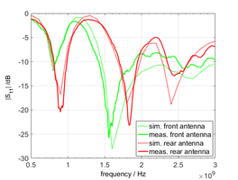
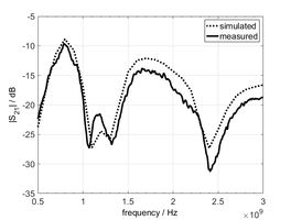
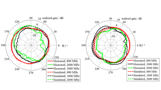
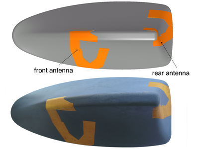
Fig. 1 shows the simulation model of the optimized arrangement and the realized prototype. Realizing the prototype antenna an injection mold was made which is suitable for the LDS-capable material Vectra E840 i LDS (Celanese GmbH) a liquid crystal polymer (LCP) that is characterized by its low losses. The permittivity was determined for the frequency f = 2.69 GHz at ɛr = 4.2 with a loss angle of tan d = 0.0027. In this case, it is necessary to consider that this material is an anisotropic material and that the specified values apply to a predominant orientation of the electrical field in parallel to the injection direction. The metallization was performed using the LDS process with a copper metallization and a nickel/gold layer to reduce surface oxidization.
Fig. 2 shows the measurement results compared to the simulation results for both antennas on a 1 m x 1 m aluminum plate. It can be seen that the input reflection coefficient as well as the coupling reveal a good match between the simulation results and the measured values. The radiation characteristics only show a slight deviation between the simulation and measurements for the arrangement of the front antenna at 1800 MHz and 2600 MHz, which is however presumably due to edge effects on the grounding surface. The results shown imply that the simulations carried out have predicted the behavior of the antennas well in spite of their multi-dimensionally curved surface, and that the simulation model has been accurately reproduced in practice.
References
[1] A. Posselt, A. Friedrich, L. Ekiz, O. Klemp, B. Geck (2014): System-Level Assessment of Volumetric 3D Vehicular MIMO Antenna Based on Measurement, The 3rd International Conference on Connected Vehicles & Expo (ICCVE 2014), Vienna, Austria, November 3-7, 2014
[2] A. Friedrich, B. Geck, O. Klemp, A. Posselt, I. Kriebitzsch (2014): 3D-Antennensysteme - Design und Validierung, ATZ-Elektronik 9, Nr. 6, S. 44-51, Springer Vieweg, Dezember 2014
[3] A. Friedrich, O. Klemp, B. Geck (2014): 3D-MID Antenna Design for Automotive Applications, 11th International Congress Molded Interconnect Devices 2014, Nuremberg/Fuerth, Germany, September 24-25, 2014
[4] O. Klemp, A. Friedrich, B. Geck, A. Posselt (2014): 3D-Antennensysteme - Anforderungen an die Fahrzeugintegration, ATZ - Automobiltechnische Zeitschrift 116, Springer Vieweg, Nr. 12, S. 60-65,
[5] A. Friedrich, B. Geck, O. Klemp, H. Kellermann (2013): On the Design of a 3D LTE Antenna for Automotive Applications based on MID Technology, European Microwave Conference 2013 (EuMC 2013), Nürnberg, Deutschland, October 6 - 11, 2013


