Considering future RF applications the possibility gained of LDS manufacturing can be applied to integrate waveguide fed antenna structures directly into plastic parts, combining the functionality of a mechanical (e.g. housing, plastic cover) as well as an electrical part. Another advantage of directly integrating antennas in plastic parts is that the transitions between the antenna, air and other plastic or metal parts in the housing, causing reflections and thereby also losses, can be reduced. In case of a direct integration of the antenna the electromagnetic wave can directly be radiated by or out of the plastic part. It has to be considered that this only applies to radiating structures where the main radiation takes place in the areas that are connected to the outer plastic part or housing. As an example in Fig.1 schematic sketch of a possible future device with an integrated antenna and a transceiver circuitry is shown.
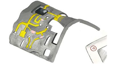
To reduce the height of the circuitry parts, like e.g. a packaged transceiver chip, a recess can also be designed into the plastic part like it is done in the generic sketch (Fig.1). The required metallization for RF transmission lines and DC feeding circuitry lines are directly applied on the plastic part that additionally builds the frame of a possible plastic housing. An example antenna development is done for an operation frequency in IEEE WIFI 802.11ad short range data transmission (WiGig).
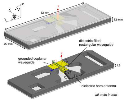
The plastic material is set to the values used for the prototype antenna, Xantar LDS 3730. (εr =2.9, tan δ = 0.007). The respective simulation model is shown in Fig. 2. The plastic part of the integrated antenna (grey) is covered from the upper and the bottom side with plastic plates (white). So the antenna is fully integrated into the plastic part. The simulated results for the input reflection coefficient are shown in Fig.3a. The antenna provides an input reflection coefficient below -10 dB from 57 GHz up to 64 GHz and a input reflection coefficient below -8 dB from 64 GHz up to 66 GHz. The radiation characteristics in the H- and E-plane is depicted in Fig. 3b. As expected the antenna shows a directive pattern. In the H-plane the radiation characteristic shows a relatively small main lobe while in the E-plane a wider main lobe is achieved. The realized peak gain over the 60 GHz WiFi/WiGig frequency range shows a relatively smooth curvature and a maximal variation of about 2.2 dB (Fig.3c). The investigations give a first insight into the possibilities provided by 3D LDS fabrication for future RF antennas in millimeter wave range.
-
Fig. 3a: Simulated input reflection of integrated waveguide fed antenna


References
[1] A. Friedrich, M. Fengler, A. Fischer, B. Geck (2016): 24 GHz Dielectric Filled Waveguide Fed Horn Antenna Using 3D-LDS MID Technology, European Microwave Conference (EUMC 2016), London, Germany, October 3-7, 2016
[2] A. Friedrich, M. Fengler, B. Geck (2016): LDS Manufacturing Technology for Next Generation Radio Frequency and Sensor Applications - A discussion on Requirements and Solutions -, 12th International Congress Molded Interconnect Devices 2016, Würzburg, Germany, September 28-29, 2016
[3] A. Friedrich, M. Fengler, B. Geck, D. Manteuffel (2017): 60 GHz 3D Integrated Waveguide Fed Antennas Using Laser Direct Structuring Technology, European Conference on Antennas and Propagation 2016 (EuCAP 2017), Paris, France, March, 2017


