One example of antennas that can be efficiently used for applications in millimeter wave range are dielectric filled waveguide fed antennas. In contrast to typical air filled waveguides often realized with a rectangular or circular cross section, for a LDS manufacturable version the dielectric LDS plastic forms the waveguide together with the LDS metallization that is applied on the outer surface. An additional advantage of the LDS fabrication is that a direct combination of a circuit board and the dielectric filled waveguide is possible. For the radiating antenna element typical principles of waveguide fed structure can be used. Dielectric rods and the different kind of lens type structures as well as dielectric and dielectric coated horn antennas to only name some; can be efficiently manufactured with the LDS process. The relatively simple fabrication process of such structures using the LDS method indicates the usability for future millimeter wave applications in consumer or automotive sensor applications. To evaluate the approach and the fabrication with the LDS process a test structure is developed and realized. The structure consists out of a grounded CPW that directly feeds the dielectric filled waveguide. As radiating element, a dielectric horn antenna is used. The test antennas are realized covering frequencies in 24 GHz ISM Band and at 77 GHz Band that is used for automotive short range radar system. Fig. 1 shows the two realized test antennas The substrate material used is Xantar LDS 3730.
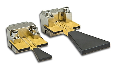
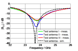
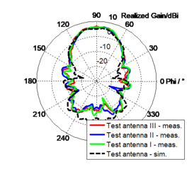
Fig. 2a: Input reflection coefficient and radiation pattern of 24 GHz dielectric horn antenna
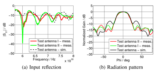
Both test antennas were characterized concerning their RF properties. A detailed description of the horn antenna at 24 GHz can be found in [1]. Fig. 2 shows the measured and simulated results for the input reflection coefficient and radiation pattern at 24 GHz (Fig. 2a) and 77 GHz (Fig. 2b). There were 3 test antennas measured. It can be seen that the agreement between measurements and simulation is good for both, the radiation pattern in the main lobe direction and the input reflection coefficient. Furthermore, a good match between the three fabricated test antennas is achieved. In conclusion this indicates the reliability of the LDS technology even in millimeter wave frequency range. The main scope designing the test structures is for verification of LDS fabrication. The structures have to be kept relatively simple. This is the reason why the test antennas are not in an optimized state. For future application-oriented configurations the advantages of the LDS technology can e.g. be applied by a 3D surface impedance metallization on a 3D shaped antenna structure. In doing so, the flexibility of the 3D manufacturing can be used to develop efficient structures and face the challenges arising for future RF devices.
References
[1] A. Friedrich, M. Fengler, A. Fischer, B. Geck (2016): 24 GHz Dielectric Filled Waveguide Fed Horn Antenna Using 3D-LDS MID Technology, European Microwave Conference (EUMC 2016), London, Germany, October 3-7, 2016


