


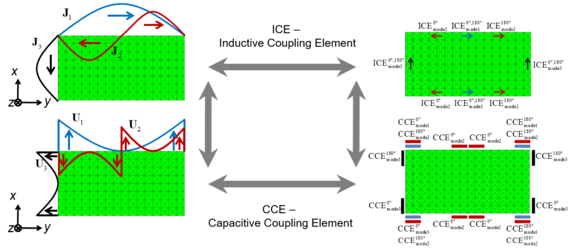
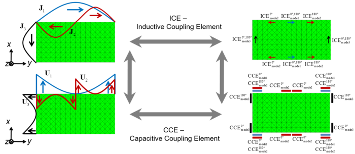
Fig. 1: Coupling elements for the excitation of characteristic modes. © 2011 IEEE [1].
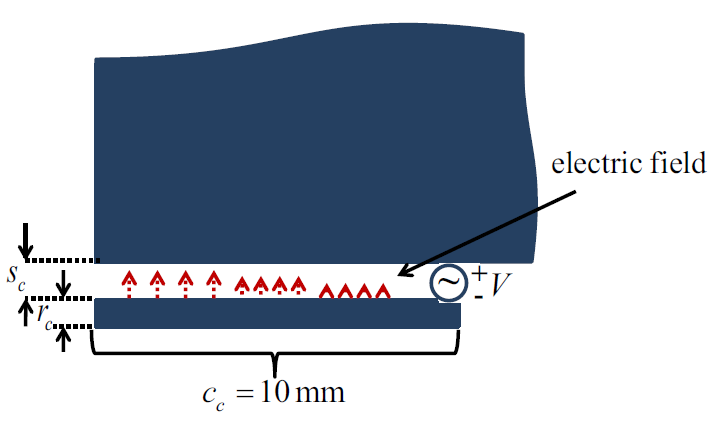
Capacitive coupling elements are generally defined as electrically small or resonant structures which are located in close vicinity to the actual antenna, thus forming some kind of capacitor, as illustrated in Fig. 1(a). Effective coupling is achieved if the coupler is placed where the electric field of the desired characteristic mode has a maximum, as depicted in Fig. 2. This corresponds to a current minimum.
Capacitive coupling is especially suitable for the excitation of several characteristic modes. If e.g. a rectangular plate is considered, most characteristic modes have current nulls in the four corners. These modes may be excited simultaneously if a capacitive coupler is placed in one of the corners. As the excited modes in general have different resonant frequencies, broadband or multi-band operation can be achieved.
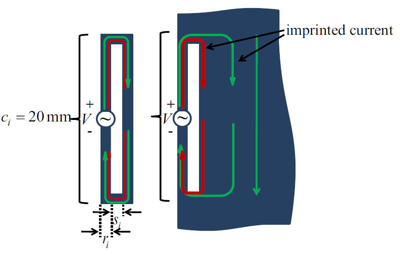
Inductive coupling is obtained by small current loops which couple to the characteristic current of a mode primarily via the magnetic field (inductively). Such couplers are typically realized as electrically small (non-resonant) slots within the antenna structure, as shown in Fig. 1(b). The coupling is most effective if the coupling element is placed where the surface current has a maximum, as illustrated in Fig. 2.
Inductive coupling has been shown to be a promising alternative for the selective excitation of characteristic modes in MIMO applications. In an iterative process, an inductive coupler is placed in a maximum of the desired mode where the other significant modes have a current minimum. This way, the desired modes can be excited with high purity and low mutual coupling.

References
[1] R. Martens, E. Safin and D. Manteuffel, "Inductive and capacitive excitation of the characteristic modes of small terminals," 2011 Loughborough Antennas & Propagation Conference, Loughborough, 2011, pp. 1-4, doi: 10.1109/LAPC.2011.6114141.


