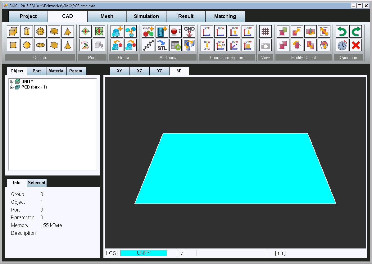
After a project has been created, the first step is to build a model. This is done in the CAD view shown in Fig. 1. For the creation of a complex antenna structure, basic geometric objects are available which may be modified by geometric transformations (translate, rotate, mirror, etc.) and Boolean operations (merge, cut, etc.). More sophisticated models can make use of local coordinate systems. Alternatively, existing models may be imported as STL-files. Other important features are the placement of excitation ports (lumped port, plane wave) and lumped elements and the assignment of material properties (conductivity, permittivity, permeability).
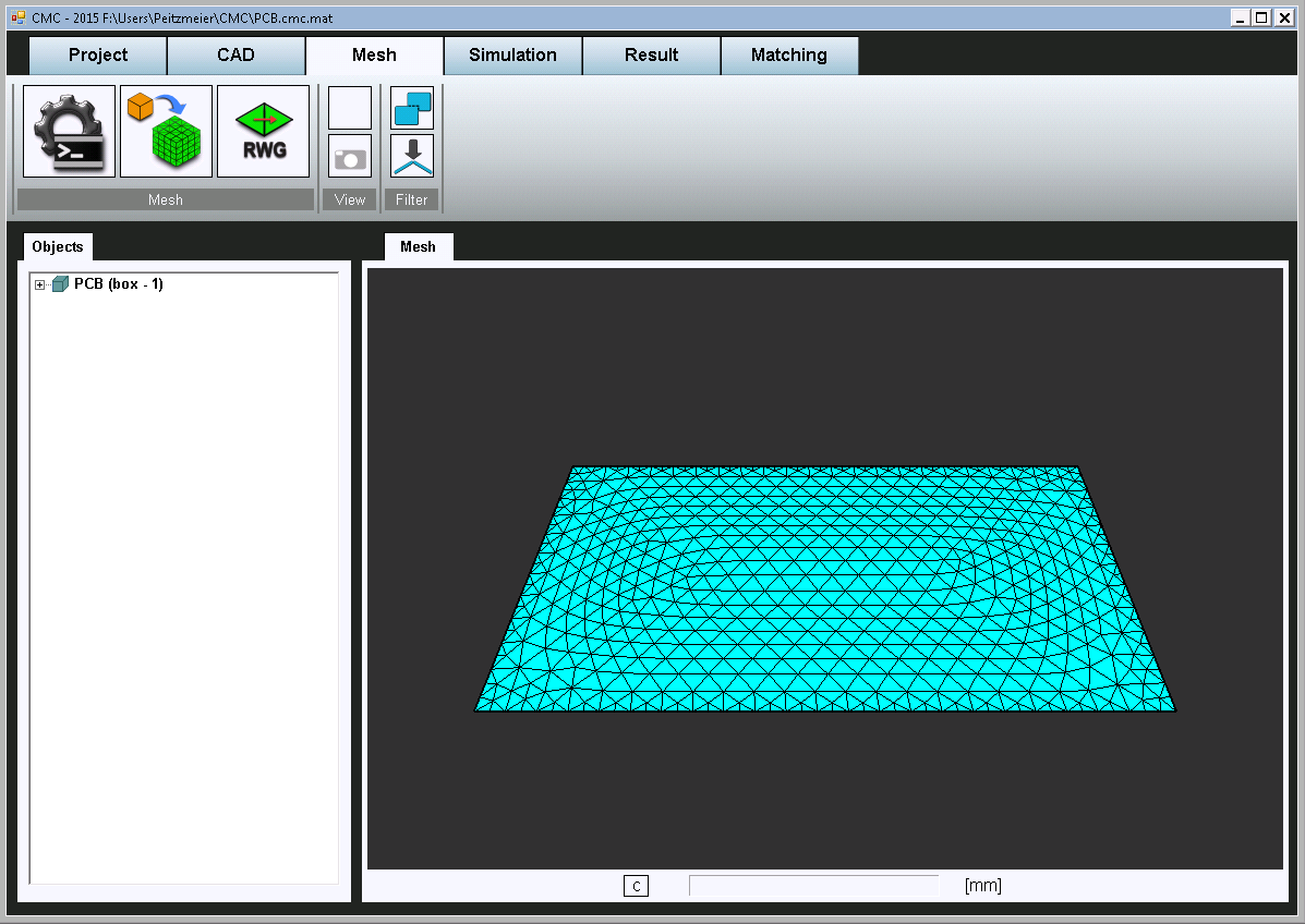
The next step is the meshing of the structure. This is done in the mesh view shown in Fig. 2. Meshing consists of compiling the CAD structure, meshing it with triangles and defining the RWG basis functions.
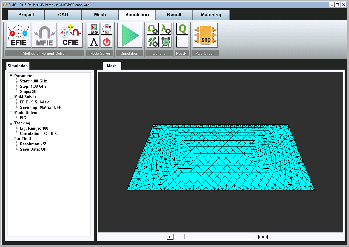
In the simulation view (Fig. 3), the simulation parameters are set. This includes the frequency range and the number of points. The integral equation, which the Method of Moments solver is based on, has to be chosen according to the structure’s geometry and material properties. Additionally, different MATLAB functions for solving the generalized eigenvalue equation are selectable. For far field calculations, the angular resolution has to be set.
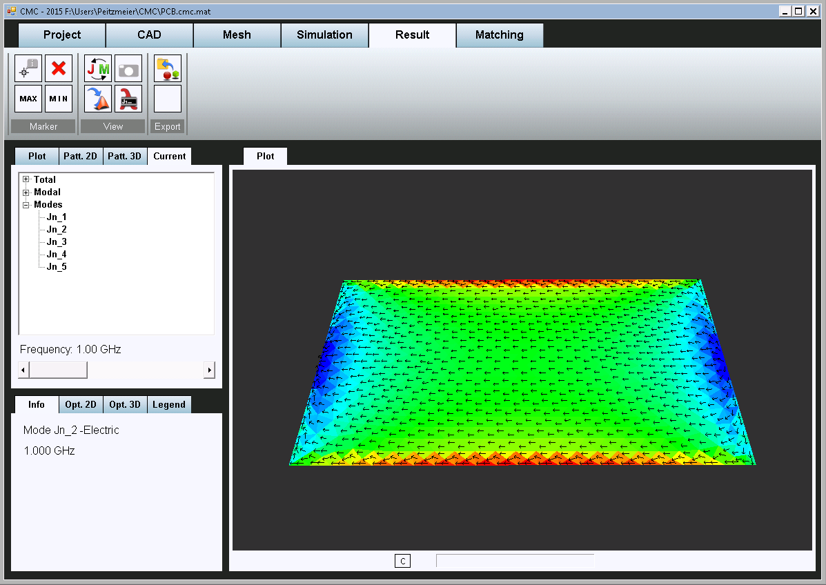
Finally, the different simulation results may be inspected in the result view (Fig. 4). The eigenvalues of the structure and other modal parameters can be plotted over frequency. Three-dimensional plots of the total and modal surface current densities and far field patterns are available as well. For advanced post processing, all simulation parameters and results are accessible from the MATLAB command window.
With CMC, HFT has participated in several benchmark programs initiated by the characteristic mode research community in order to evaluate the state of the art of characteristic mode computation [1].
-
Fig. 1: CAD view of CMC
-
Fig. 2: Mesh view of CMC
-
Fig. 3: Simulation view of CMC
-
Fig. 4: Result view of CMC
References
[1] Yikai Chen, Kurt Schab, Miloslav Capek, Michal Masek, Buon Kiong Lau, Hanieh Aliakbari, Yigit Haykir, Qi Wu, Willem J. Strydom, Nikolai Peitzmeier, Milos Jovicic, Simone Genovesi and Francesco Alessio Dicandia (2018): Benchmark Problem Definition and Cross-Validation for Characteristic Mode Solvers, 12th European Conference on Antennas and Propagation (EUCAP), London, United Kingdom, April 9-13, 2018


